Computer Controlled Machining
Assignment:
I am going to use Onhsape in onshape.com for designing my chair and it parts.
What is CNC
CNC is a Computer Numerical Control in which it is the automation of machine tools using a computer to execute pre designed shape or sequences rather than the traditional way of using lever, hand or wheel for execution.
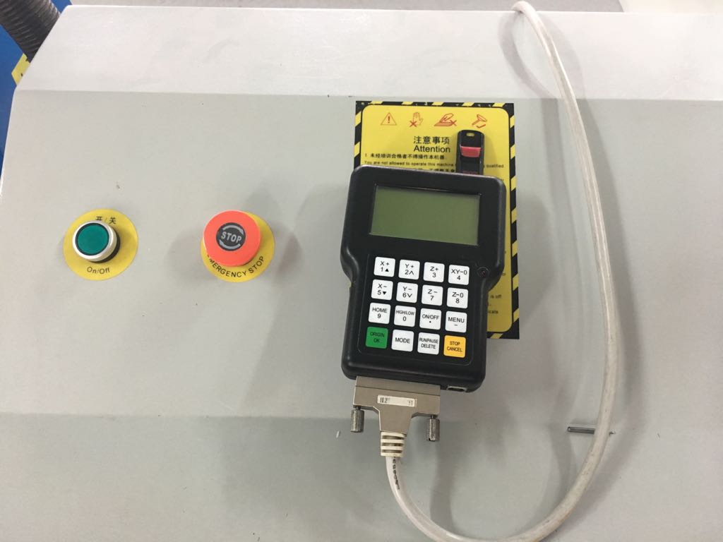
The CNC module were using is J-Cut 1325b.
Designing:
As the previous assignments before,I getting the hang on using the complicated Onshape for designing my chair.
At first I started designing my seating area as rectangular shape of 55 cm width and 30 cm hight. Then I made 4 cross shapes to fit the legs to hold the seating area. For the cross section the dimension are 6 cm height and 1.8 cm the width.
Note: The limit for thickness is 1.8 cm such the maximum thickness will be for all is 1.8 cm or less.
The link of my seating design in Onshape.com
The seating area with my name done on onshape.
For the cross shape I need to two parts and like a puzzle fit them together and then assembly them into on shape. The first part for my legs is I made a u shape with 35cm height with 5.4 width so that when assembled the seat can have the proper support and the chair is done.
The first piece of the leg is done
For the second I made a “M” shape leg to fit the with the first part to create the proper support for the chair.
The link.
To complete my assembly, the first part of “M” legs is will be connected to the second part which will be “U” shape with the same dimension made as the first leg part to support each other.
The Second piece of the leg is done
Cutting:
In the cutting phase, I have to save my designs in Onshape by exporting the file in DXF.
One of my sketches to exported to DXF
After finishing the DXF I have to convert the file to “Artcam” so that the CNC can read the file.
The uploading the my designs in Artcam I set the following parameters in the program: Our CNC settings : converting my design the file to Art cam
1) Tool type end mill
2) Diameter 3 mm
3) Steover 1.2 mm
4) Stepdown 3 mm
5) Feed rate 75 mm/sec
6)spindle speed 15,000 rpm
7) Plunge rate 50 mm/sec
Our CNC machine
•.
Note: The CNC does not work electronically and were waiting for maintenance team to fix.
Artcam file for chair
Leg 1 PLT File
Leg 2 PLT File
Changing the the machine
Due to the unexpected circumstances I changed my design dimension innn artcam to fit the CNC limit of 60 X 60 cm. I used the J-cut model 6060 for my design.
The CNC model
The dimension for the legs changed to fit the limit 30 cm by 5.4 cm. The chair dimension changed to 35 cm to 55 cm.